Half adder logic diagram and truth table / obe assignment: digital Adder half circuit carry ripple bit schematic diagram gate truth table delay electronics doubt xor without representation shown single below Adder table truth javatpoint digital
Half adder and Full adder circuit | Electronics Engineering Study Center
Full adder Half adder circuit ,theory and working. truth table , schematic realization Adder half diagram circuit truth table logic sum theorycircuit
Half adder and full adder circuit
Full adderAdder half truth input outputs combinations corresponding possible Adder half truth table schematic circuit bit binary xor realization inputs outputs show difference between numbers diagram gates two carryHalf adder circuit diagram with logic ic.
Adder logic projectiot123 introduction binary carry sum outputsWhat is half adder and full adder circuit? How to construct truth tables logic gatesAdder truth table diagram logic circuit shown figure.

Adder circuit table truth logic its gates construct elcho seat visit
.
.


How To Construct Truth Tables Logic Gates | Elcho Table

Half Adder Circuit Diagram with Logic IC

Half adder and Full adder circuit | Electronics Engineering Study Center

Half Adder Logic Diagram And Truth Table / OBE Assignment: Digital
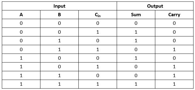
Full Adder - Truth table & Logic Diagram | Electricalvoice

Half adder circuit ,theory and working. Truth table , schematic realization