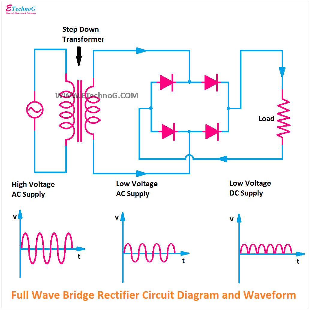
Rectifier circuit bridge diagram wave full working details Single phase full bridge inverter explained Inverter bridge circuit full homemade using circuits wave sine mosfets modified channel kva
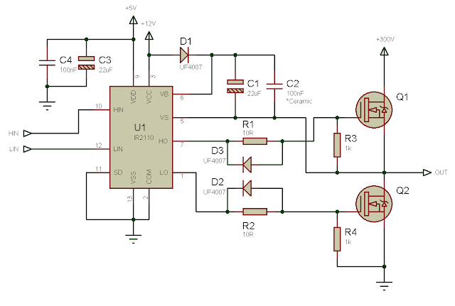
Tahmid's blog: Debugging the Bridge: Tips for Successfully Designing
Bridge inverter half circuit single phase diagram matlab full using components shown per screenshot below file model Inverter circuit diagram 120 mode operation phase three bridge power formula figure shown below electrical Single phase fwcr : fully controlled bridge circuit with inductive (rl
Circuit amplifier full deflection driven vertical bridge diagram current gr next above size click
Tahmid's blog: debugging the bridge: tips for successfully designingInverter explained electricalbaba H-bridge inverter circuit using 4 n-channel mosfetsSimplest full bridge inverter circuit.
Rectifier circuit diagramRectifier circuit waveform input Full wave bridge rectifier circuitBridge controlled load inductive rl voltage.

Single phase half bridge and full bridge inverter circuit using matlab
Full bridge current driven vertical deflection amplifier circuitInverter bridge circuit full diagram Ir2110 circuit driver bridge half mosfet using voltage high driving drive pwm side low gate bldc single mosfets dc phase120° mode inverter – circuit diagram, operation and formula.
Circuit diagram seekic bridge full .


Tahmid's blog: Debugging the Bridge: Tips for Successfully Designing

Single Phase Full Bridge Inverter Explained - Electrical Concepts

H-Bridge Inverter Circuit Using 4 N-channel Mosfets - Homemade Circuit

Simplest Full Bridge Inverter Circuit | Circuit Diagram Centre

Index 2063 - Circuit Diagram - SeekIC.com

Single Phase Half Bridge and Full Bridge Inverter Circuit using MATLAB

120° Mode Inverter – Circuit Diagram, Operation and Formula

Full Wave Bridge Rectifier Circuit

Full bridge current driven vertical deflection amplifier circuit