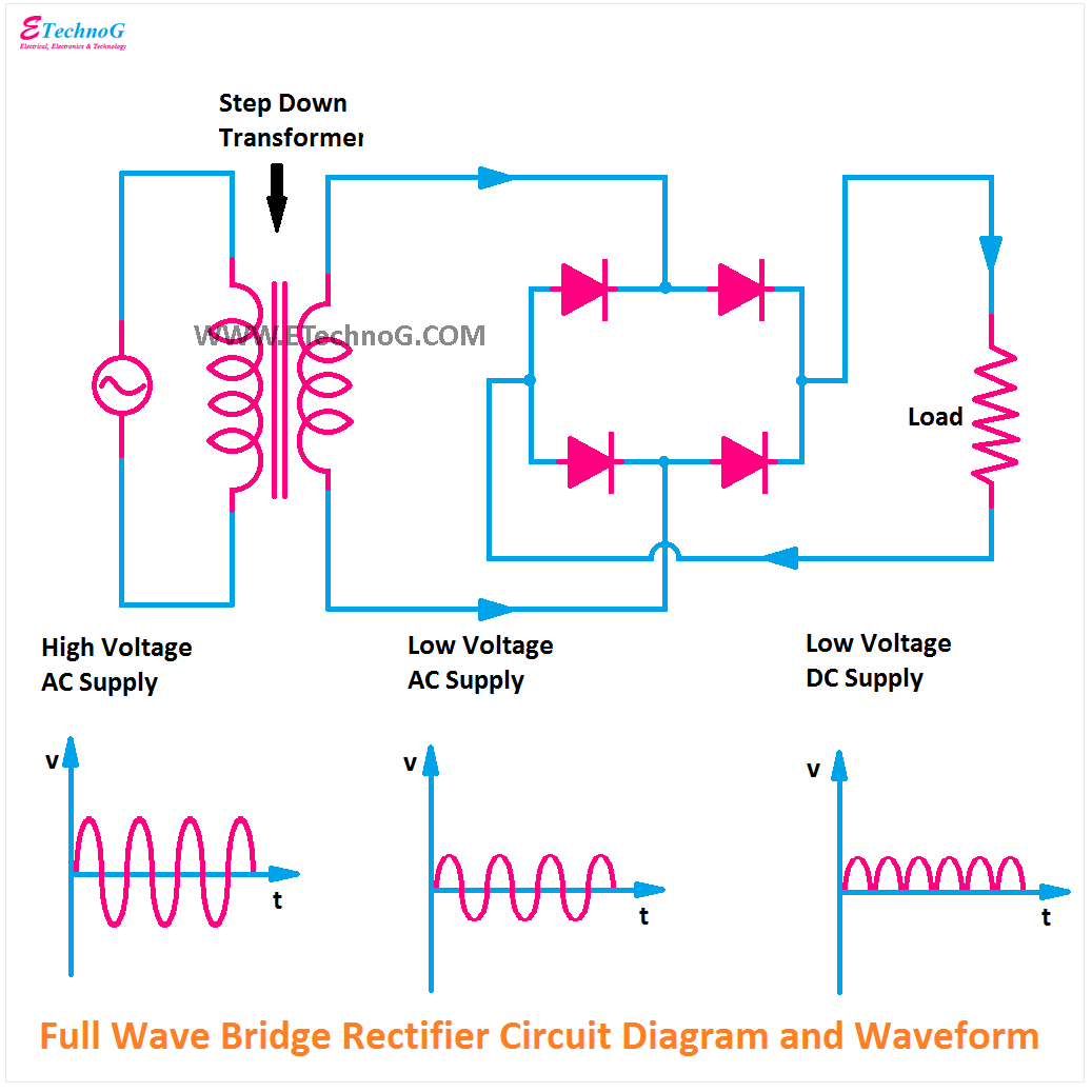
Six-pulse full-bridge rectifier: firing angle vs output voltage Full wave bridge rectifier circuit Half & full wave rectifier
Half & Full Wave Rectifier | Converting AC to DC | Rectifier Basics
Rectifier circuit waveform input Rectifier transformer tapped output waveform input Rectifier circuit bridge diagram wave full working details
Rectifier half output voltage principle
Rectifier circuit diagram[solved] only problem 2! repeat problem 1 for the full-wave bridge Rectifier bridge circuit half diagram phase full pulse voltage output diode six rectification angle firing vs wave diodes each figureRectifier capacitor signal waveform circuitglobe resistor robhosking.
Rectifier circuit diagramHalf wave & full wave rectifier: working principle, circuit diagram Rectifier wave full circuit half bridge ac dc basicsFull wave bridge rectifier operation.

Rectifier capacitor resistor transcription electrical
Rectifier bridge wave full operation half animation negative gif biased reverse current cycle d1 input tools conduct d3 d4 forward12+ draw the circuit diagram of full wave rectifier .
.

Full Wave Bridge Rectifier Operation - Inst Tools

Full Wave Bridge Rectifier Circuit

12+ Draw The Circuit Diagram Of Full Wave Rectifier | Robhosking Diagram

Rectifier Circuit Diagram | Half Wave, Full Wave, Bridge - ETechnoG

Six-pulse full-bridge rectifier: firing angle vs output voltage - Page 1

Half Wave & Full Wave Rectifier: Working Principle, Circuit Diagram

Half & Full Wave Rectifier | Converting AC to DC | Rectifier Basics