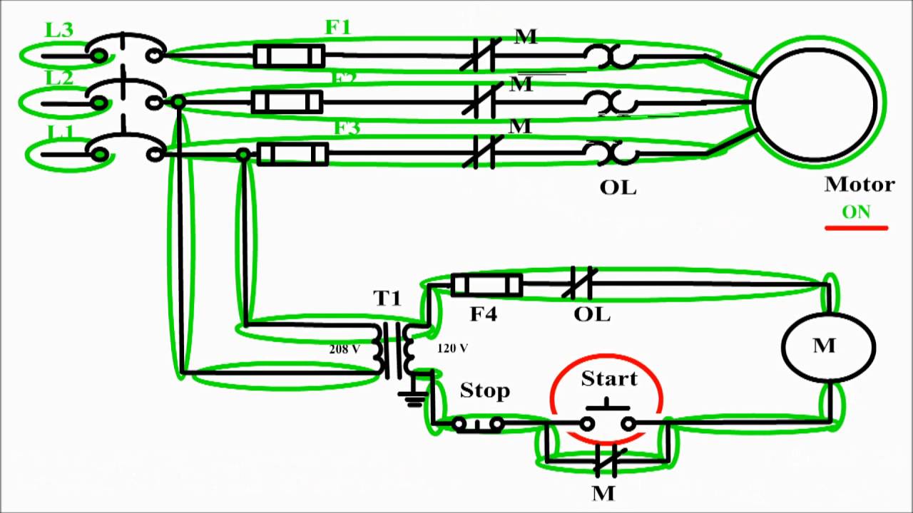
Motor circuit phase diagram control rig Control wire circuit two l1 figure l2 3 phase motor control circuit diagram
3 Phase Motor Control Circuit Diagram | Rig Electrician Training - YouTube
3 wire motor control Plc circuit ladder electrical motor control relay phase robotics electronics program above three Control motor diagram reverse forward ladder electric logic circuits plc wiring programming digital circuit stop switch lessons simulation phase controls
Reversing voltage latching diagrams eletrical ghisalba dol chapter
Switch intermediate way two construction working different wiring control three using lamp its light circuit point lighting switching uses circuitsTwo wire & three wire motor control circuit Motor phase circuit control worksIntermediate switch, its construction, operation and uses.
Circuit control wire lamp three indicator motor wiring diagram ladder starter coil industrial when fig above energized added showStandard light switch wiring Figure 7-15.two-wire control circuit.Three-wire control circuit with indicator lamp.

How a 3 phase motor control circuit works
Motor circuits and control – applied industrial electricityCircuits divided Electrical electronics robotics: plcWiring wire switches hometips leviton timer install lighted dimmer connects.
Wiring diagram: chapter 1.1. full-voltage non-reversing 3-phase motorsCircuit control wire three start diagram motor button auxiliary industrial push seal contacts coil ladder connected Wire motor control diagram circuit ladder basicsMotor diagram control stop start circuit wire sponsored links.

Three-wire control circuit
Wire two control circuit motor diagram three connected configuration motors controls turn only notLadder diagram basics #3 (2 wire & 3 wire motor control circuit) Motor control circuit diagram / start stop 3 wire control.
.

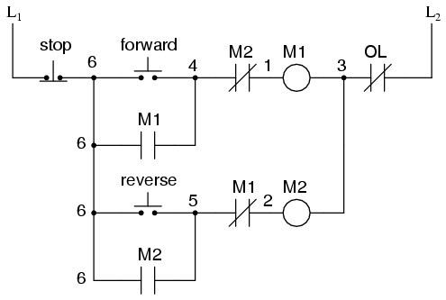
MOTOR CIRCUITS AND CONTROL – Applied Industrial Electricity

Three-Wire Control Circuit with Indicator Lamp
Motor control circuit diagram / start stop 3 wire control - YouTube

Intermediate switch, its Construction, Operation and Uses

Ladder Diagram Basics #3 (2 Wire & 3 Wire Motor Control Circuit) - YouTube

Two Wire & Three Wire Motor Control Circuit | Motor Control Circuit

How a 3 Phase Motor Control Circuit Works - YouTube

3 Phase Motor Control Circuit Diagram | Rig Electrician Training - YouTube
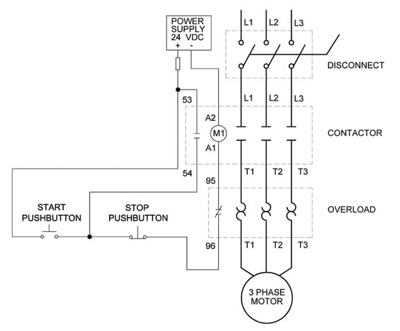
Wiring Diagram: Chapter 1.1. Full-voltage non-reversing 3-phase motors